Large Data Center projects are very power hungry. They may need to draw a power of 1.2 Giga Watt or more from the grid to run the servers. Sometimes own power generation through conventional or unconventional mode is also necessary if grid power availability is insufficient. Satcon provides the following Engineering services for the EHV / HV / MV power system of the Data Center :
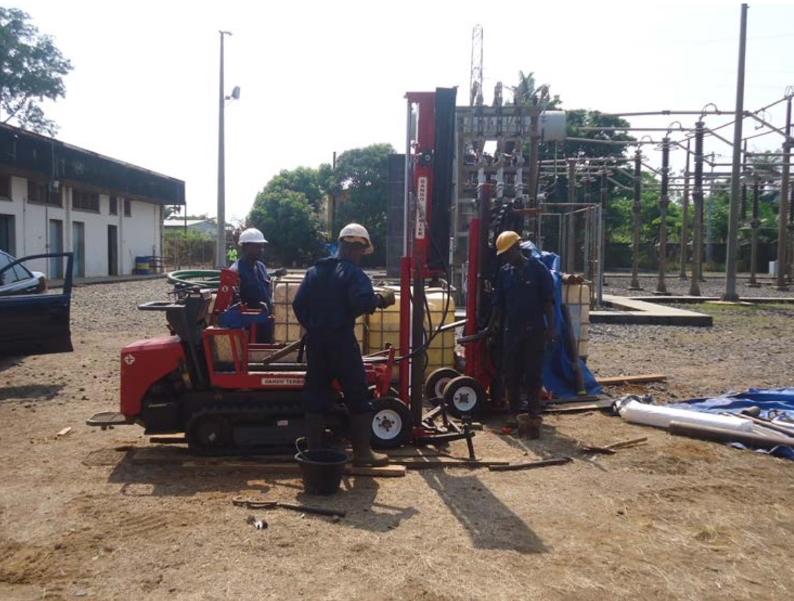
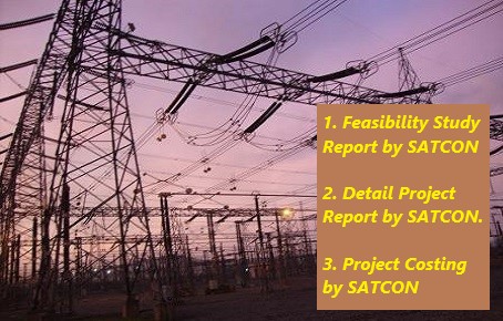
1. Feasibility study to identify the source of power supply.
2. Assistance for entering into an agreement with the local utility.
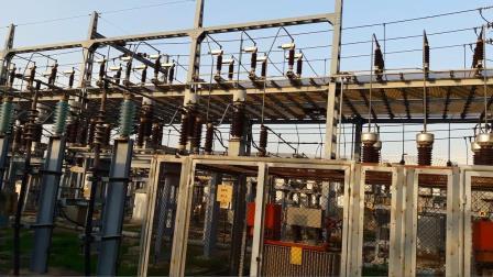
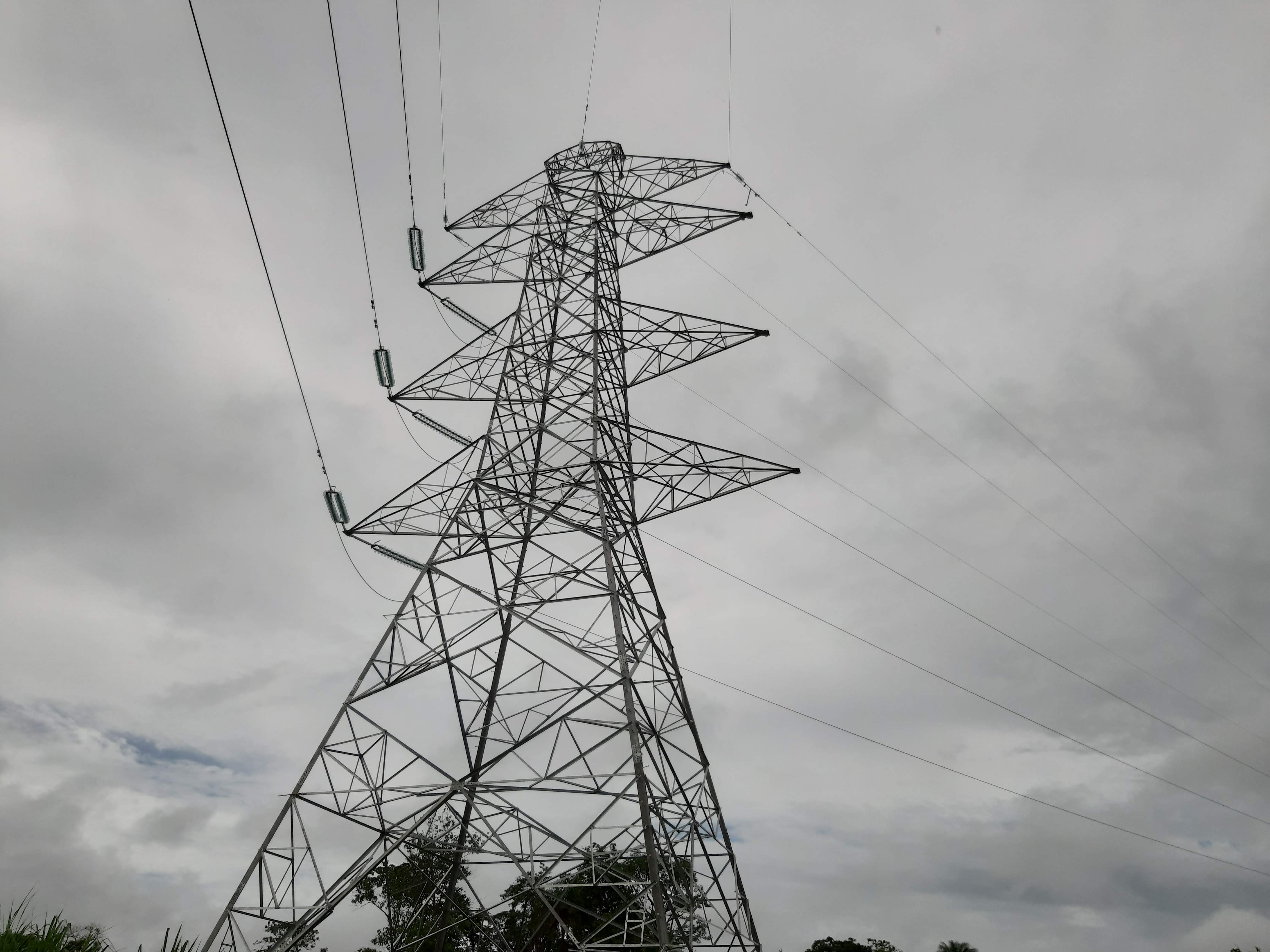
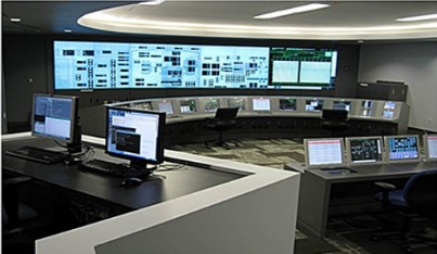
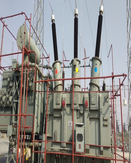
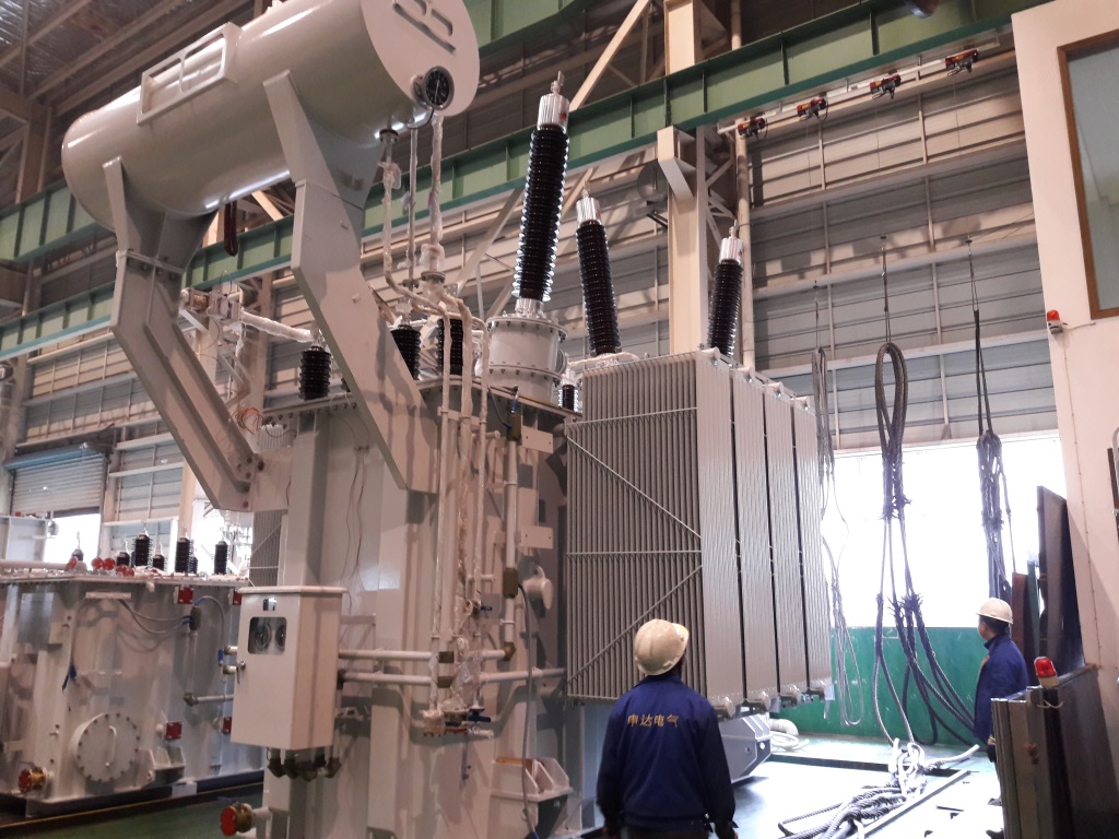
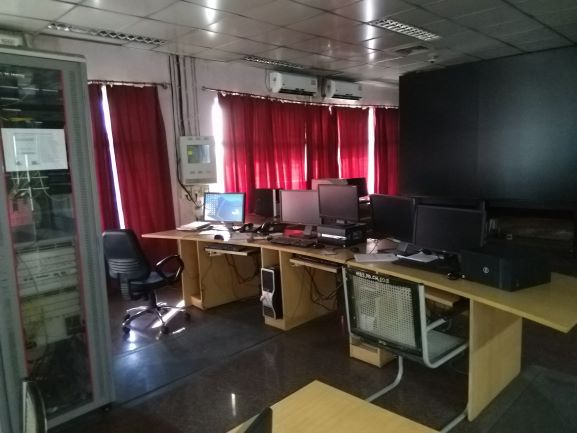
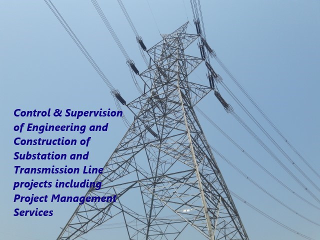
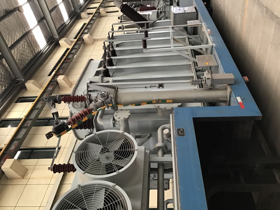
3. Providing complete consultancy and detail engineering (concept to commissioning) starting from the power drawal from the Utility substation, receiving the supply at Data center substation, appontment of contractor, stepping down the EHV voltage to a medium voltage for interconnecting with the electrical network of the Data center, complete supervision and control of the EHV substation and transmission line supply, erection, testing and commissioning.
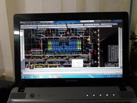
4. Following design and drawings are delivered :
4.1. Relay and Metering SLDs of EHV switchyards, MV switchgear panels, LV switchgears and Distribution boards.
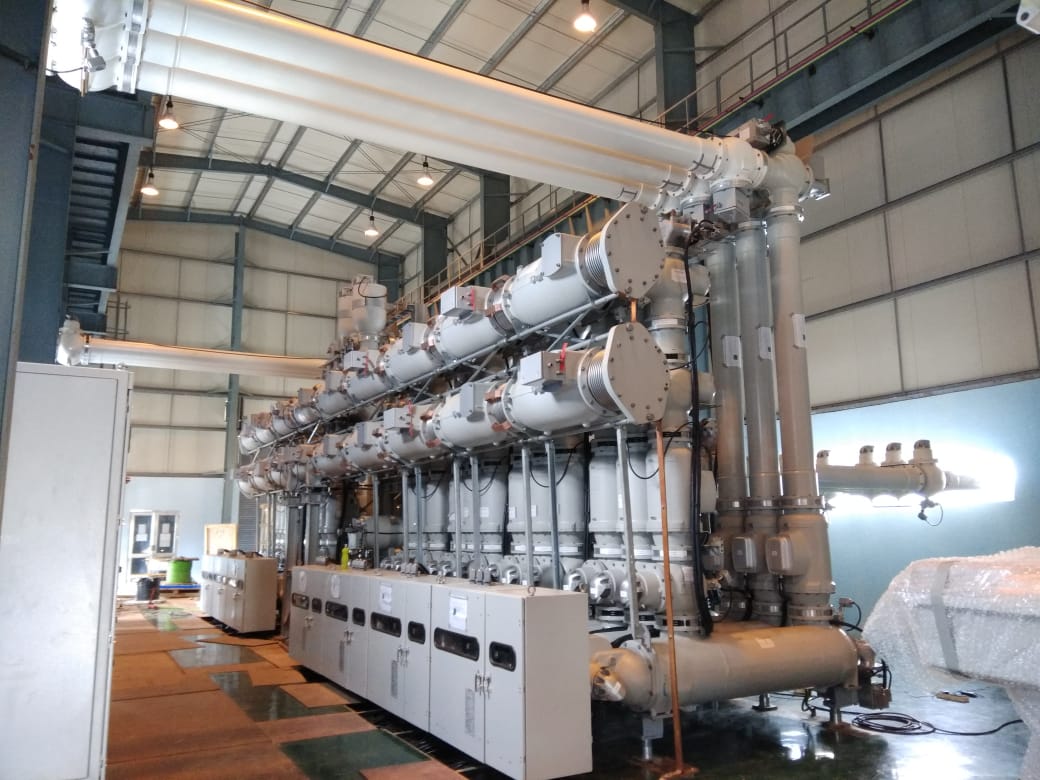
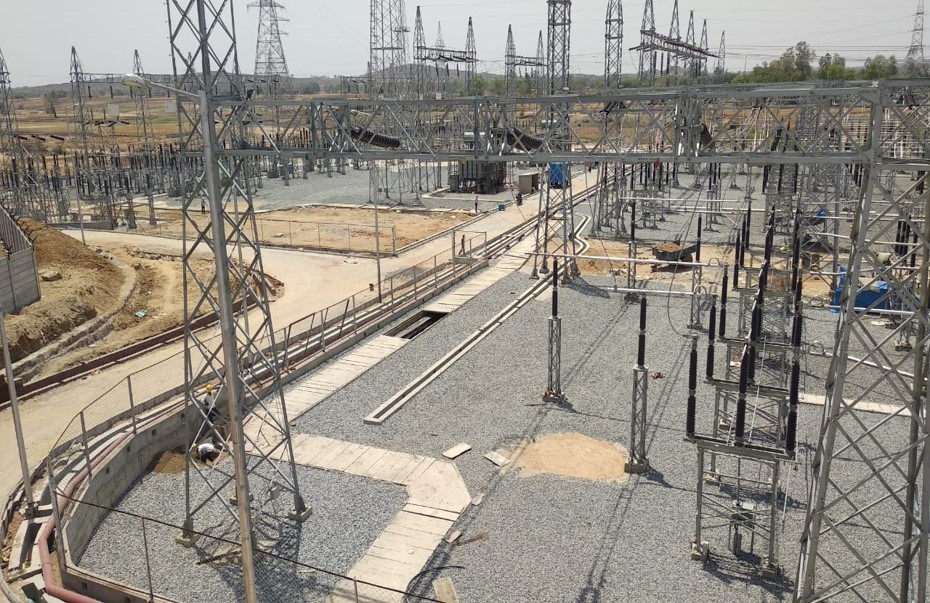
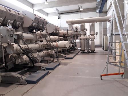
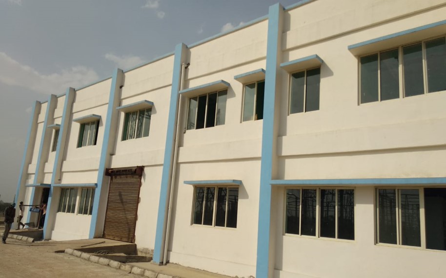
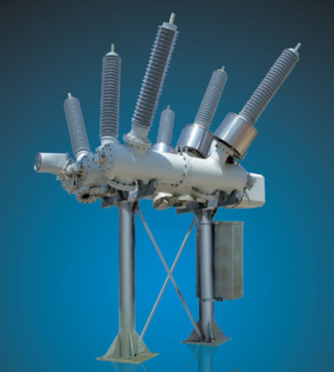
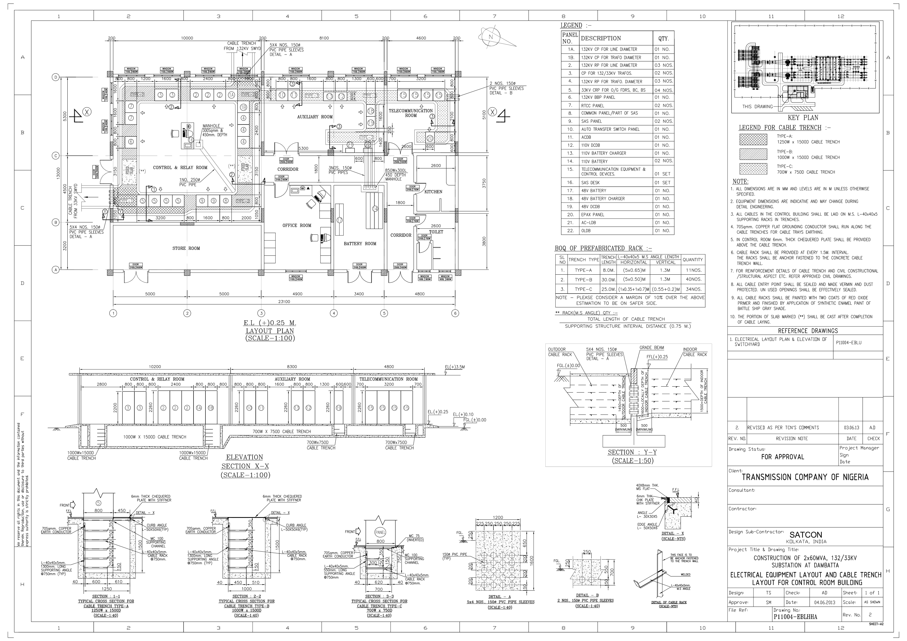
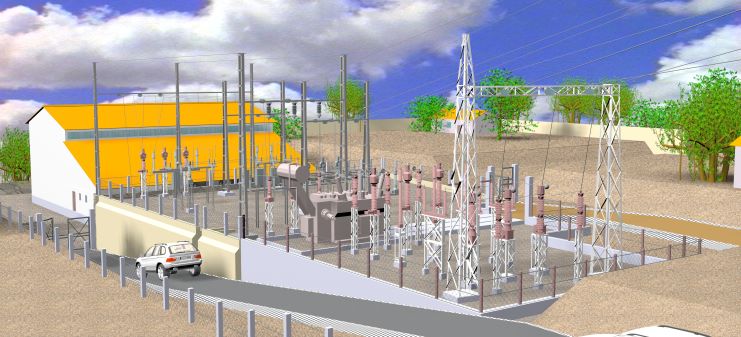
4.2. Electrical layout plan & elevation of AIS / GIS EHV switchyards, GIS substation buildings, Control buildings and plant electrical rooms.
4.3. Erection key diagram of EHV switchyards along with BOQ of clamps, connectors, conductors, shield wires, hardwares.
4.4. Clearance diagram for EHV switchyards.
4.5. Cable trench layout with BOQ of cable trays, bends, Tee, reducers, cable racks etc. for AIS / GIS EHV switchyards, GIS substation buildings, Control buildings and plant electrical rooms.
4.6. Earthing calculation and earthing layout with BOQ of all earthing materials for EHV switchyards, GIS substation buildings, Control buildings and plant electrical rooms.
4.7. Direct stroke lightning protection (DSLP) calculation and layout of EHV switchyards, GIS substation buildings, Control buildings and plant electrical rooms.
4.8. Interlocking diagrams for 400kV, 220kV, 132kV, 33kV switchyards. Protection trip logics.
4.9. Control cable block diagrams and estimation.
4.10. Power cable schedule and interconnection chart.
4.11. Control cable schedule and interconnection chart.
4.12. Earthing and Lightning protection design calculations, drawings and BOQ.
4.13. Lighting calculations, SLD for lighting distribution and layout with BOQ of lighting materials for outdoor switchyard, road, open areas, substation buildings, staff quarters, Control buildings, etc.
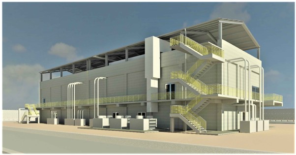
4.14. Civil drawings of equipment and gantry tower foundations, Control building, Switchgear building, Store shed, DG building, Security room, Transformer oil pit and drain away system, Oil water separator pit, Rail cum Road, Cable trench, Surface drainage system, Boundary wall, Fence, Fence gate.
4.15. Steel structure for Gantry towers, Beams and Equipment supports (Lattice / Pipe type).
4.16. SCADA system Architecture, Technical specification and BOQ.
4.17. PLCC system Architecture, Technical specification and BOQ.
4.18. Fiber Optic communication system Architecture, Technical specification and BOQ.
4.19. Air conditioning and ventilation systems.
4.20. Fire protection system, hydrant and High velocity water spray (HVWS) systems,
4.21. Fire detection and alarm system.
4.22. Nitrogen injection fire protection systems.
4.23. Technical spec of all equipment, materials ansd works.
5. Bid evaluation and recommendation reports.
6. Vendor drawing review and approval.
7. Project management services.