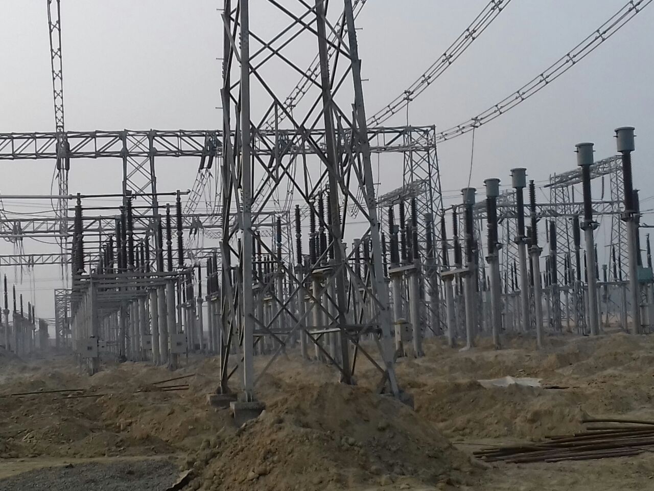
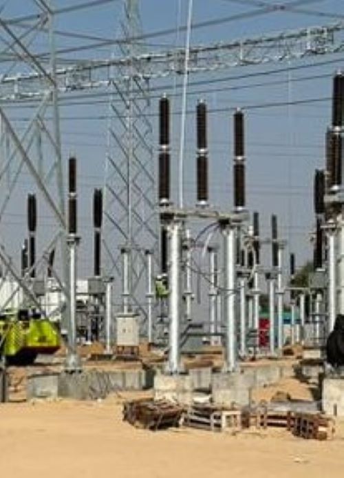
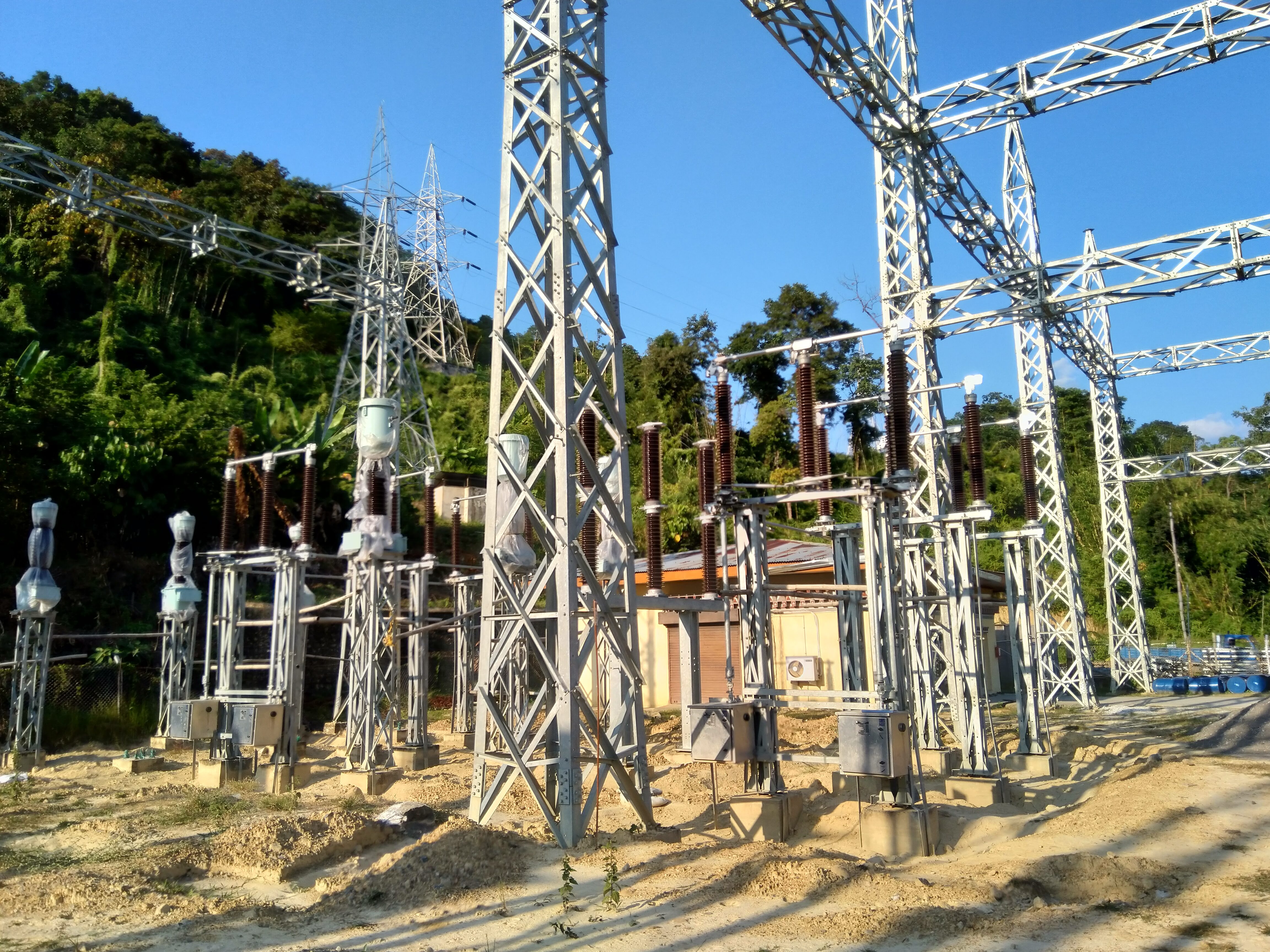
Engineering Consultant for Design, Engineering and Consultancy Services for Extra High Voltage Substations, Transmission Lines, Electrical Balance of Plant (EBOP) of Thermal Power Plants, Large Electrical Systems (HV/MV) of Steel plants, Coal & Iron Handling Plants & Misc. Industries, Electrical System studies using ETAP 2020.
A. | ELECTRICAL DRAWINGS : | |||
1 | SLD | |||
1.1 | Key SLD - 132/33kV Substation | A0 | 1 | NO. |
1.2 | 132/33kV Switchyard - Protection & Metering SLD | A0 | 1 | NO. |
1.3 | SLD - 415V Main Switchboard | A2 | 1 | NO. |
1.4 | SLD - 415V ACDB | A2 | 1 | NO. |
1.5 | SLD - 415V MLDB | A3 | 1 | NO. |
1.6 | SLD - 415V Emergency LDB | A3 | 1 | NO. |
1.7 | SLD - 250V DCDB | A2 | 1 | NO. |
1.10 | SLD - 48V DCDB | A3 | 1 | NO. |
1.11 | SLD - Bay Marshalling Kiosk - 132kV | A3 | 1 | NO. |
1.12 | SLD - Bay Marshalling Kiosk - 33kV | A3 | 1 | NO. |
2 | ELECTRICAL LAYOUT & ELEVATION, EKD | |||
2.1 | Land Utilization Plan - 132/33kV Substation | A0 | 5 | NO. |
2.2 | Switchyard Layout - Plan of 132/33kV Switchyard | A0 | 5 | NO. |
2.3 | Switchyard Layout - Elevation of 132/33kV Switchyard | A0 | 5 | NO. |
2.4 | Erection key diagram - Plan of 132/33kV Switchyard | A0 | 2 | NO. |
2.5 | Erection key diagram - Elevation of 132/33kV Switchyard | A0 | 2 | NO. |
2.6 | Electrical Equipment Layout with Cable Trench Details - Control Building | A1 | 2 | NO. |
3 | CABLE ROUTING, TRAY & TRENCH LAYOUT AND DETAILS | |||
3.1 | Switchyard Cable Trench (RCC) Layout and Sections with BOM of Cable Trays | A0 | 2 | NO. |
4 | EARTHING LAYOUT & DETAILS | |||
4.1 | Earthing Layout & BOM of 132/33kV Switchyard | A0 | 1 | NO. |
4.2 | Earthing Layout - Control building | A1 | 1 | NO. |
5 | LIGHTNING PROTECTION LAYOUT & DETAILS | |||
5.1 | Switchyard DSLP layout and BOM | A0 | 1 | NO. |
5.2 | Lightning Protection Layout with BOM for Control Building | A2 | 1 | NO. |
6 | ILLUMINATION AND SMALL POWER LAYOUT | |||
6.1 | Switchyard Illumination Layout, SLD and BOM | A0 | 1 | NO. |
6.2 | Illumination and small Power Layout, SLD and BOM - Control building | A1 | 2 | NOS. |
6.3 | Illumination layout, SLD and BOM - Switchyard roads and approach road | A1 | 1 | NO. |
6.4 | Illumination and small power layout, SLD and BOM - Store | A3 | 1 | NO. |
6.5 | Illumination and small power layout, SLD and BOM - DG room | A3 | 1 | NO. |
6.6 | Illumination and small power layout, SLD and BOM - Pump house | A3 | 1 | NO. |
6.7 | Illumination and small power layout, SLD and BOM - Security room | A3 | 1 | NO. |
7 | CONTROL SCHEMATICS & BLOCK DIAGRAMS | |||
7.1 | 132KV Intelocking Logic Diagram at BMK | A4 | 2 | NOS. |
7.2 | 33KV Intelocking Logic Diagram at BMK | A4 | 2 | NOS. |
8 | CABLE SCHEDULE & INTERCONNECTION DIAGRAMS | |||
8.1 | 132kV switchyard - Control Cable schedule and Interconnection Diagrams | A4 | 2 | LOT |
8.2 | 33kV switchyard - Control Cable schedule and Interconnection Diagrams | A4 | 2 | LOT |
8.3 | LV Switchgear, ACDB, DCDB, MLDB, ELDB, SLDBs, BMK - Power Cable Schedule and Interconnection Diagram | A4 | 2 | LOT |
9 | SCADA & PLCC | |||
9.1 | Technical specification of PLCC system | A4 | 1 | LOT |
9.2 | Technical specification of SCADA system | A4 | 1 | LOT |
9.3 | SCADA I/O List | A4 | 1 | LOT |
9.4 | PLCC Block diagram | A1 | 1 | LOT |
9.5 | SCADA Block diagram | A1 | 1 | LOT |
B | ELECTRICAL DESIGN CALCULATIONS | |||
1 | 132/33kV Switchyard - Earthing calculation | A4 | 1 | LOT |
2 | 132/33kV Switchyard DSLP calculation | A4 | 1 | LOT |
3 | Lighting calculation - Control Building | A4 | 1 | LOT |
4 | Lighting calculation - 132/33kV switchyard | A4 | 1 | LOT |
5 | Lighting calculation - Switchyard roads | A4 | 1 | LOT |
6 | Lighting calculation - DG Room | A4 | 1 | LOT |
7 | Lighting calculation - Store shed | A4 | 1 | LOT |
8 | Lighting calculation - Pump house | A4 | 1 | LOT |
9 | Lighting calculation - Security room | A4 | 1 | LOT |
C | STRUCTURAL DRAWINGS WITH BOM AND WEIGHT AND DESIGN CALCULATIONS : | |||
C.1 | 132KV : | |||
1 | GA drawing of 132kV Line gantry tower | A1 | 1 | NO. |
2 | GA drawing of 132kV Line gantry beam | A1 | 1 | NO. |
3 | GA drawing of 132kV Transformer gantry tower | A1 | 1 | NO. |
4 | GA drawing of 132kV Transformer gantry beam | A1 | 1 | NO. |
5 | GA drawing of 132kV Main bus A-Frame structure | A1 | 1 | NO. |
6 | GA drawing of 132kV Transfer bus A-Frame structure | A1 | 1 | NO. |
7 | GA drawing of support structure for 132kV Isolator with E/S | A2 | 1 | NO. |
8 | GA drawing of support structure for 132kV Isolator without E/S | A2 | 1 | NO. |
9 | GA drawing of support structure for 132kV LA | A3 | 1 | NO. |
10 | GA drawing of support structure for 132kV CVT | A3 | 1 | NO. |
11 | GA drawing of support structure for 132kV CT | A3 | 1 | NO. |
12 | GA drawing of support structure for 132kV BPI | A3 | 1 | NO. |
13 | GA drawing of support structure for 132kV PT | A3 | 1 | NO. |
C.2 | 33KV : | |||
1 | GA drawing of 33kV Line gantry tower | A2 | 1 | NO. |
2 | GA drawing of 33kV Line gantry beam | A2 | 1 | NO. |
3 | GA drawing of 33kV Transformer gantry tower | A2 | 1 | NO. |
4 | GA drawing of 33kV Transformer gantry beam | A2 | 1 | NO. |
5 | GA drawing of 33kV Main bus A-Frame structure | A2 | 1 | NO. |
6 | GA drawing of 33kV Transfer bus A-Frame structure | A2 | 1 | NO. |
7 | GA drawing of support structure for 33kV Isolator with E/S | A2 | 1 | NO. |
8 | GA drawing of support structure for 33kV Isolator without E/S | A2 | 1 | NO. |
9 | GA drawing of support structure for 33kV LA | A3 | 1 | NO. |
10 | GA drawing of support structure for 33kV PT | A3 | 1 | NO. |
11 | GA drawing of support structure for 33kV CT | A3 | 1 | NO. |
12 | GA drawing of support structure for 33kV BPI (Low level) | A3 | 1 | NO. |
13 | GA drawing of support structure for 33kV BPI (High level) | A3 | 1 | NO. |
14 | GA drawing of support structure for 33kV HG fuse | A3 | 1 | NO. |
C.3 | STRUCTURAL DESIGN CALCULATIONS : | |||
1 | Structural design calculations - 132kV | A4 | 1 | LOT |
2 | Structural design calculations - 33kV | A4 | 1 | LOT |
D | CIVIL CONSTRUCTIONAL DRAWINGS AND DESIGN CALCULATIONS : | |||
D.1 | GENERAL : (9 x 132 kV Bay + 9 x 33 kV Bay) | |||
1 | Overall foundation layout of switchyard | A0 | 5 | NO. |
2 | Foundation details of Lightning mast | A1 | 1 | NO. |
3 | Foundation design calculations for lightning mast | A4 | 1 | LOT |
D.2 | 132KV GANTRY TOWER AND EQUIPMENT FOUNDATION DETAILS : | |||
1 | Foundation details of 132kV Line gantry tower | A2 | 1 | NO. |
2 | Foundation details of 132kV Transformer gantry tower | A2 | 1 | NO. |
3 | Foundation details of A Frame - 132kV Main bus | A2 | 1 | NO. |
4 | Foundation details of A Frame - 132kV Transfer bus | A2 | 1 | NO. |
5 | Foundation details of support structure for 132kV Isolator with E/S | A2 | 1 | NO. |
6 | Foundation details of support structure for 132kV Isolator without E/S | A2 | 1 | NO. |
7 | Foundation details of support structure for 132kV LA | A3 | 1 | NO. |
8 | Foundation details of support structure for 132kV CVT | A3 | 1 | NO. |
9 | Foundation details of support structure for 132kV CT | A3 | 1 | NO. |
10 | Foundation details of support structure for 132kV BPI | A3 | 1 | NO. |
11 | Foundation details of support structure for 132kV PT | A3 | 1 | NO. |
12 | Foundation design calculations | A4 | 1 | LOT |
D.3 | 33KV GANTRY TOWER AND EQUIPMENT FOUNDATION DETAILS : | |||
1 | Foundation details of 33kV Line gantry tower | A2 | 1 | NO. |
2 | Foundation details of 33kV Transformer gantry tower | A2 | 1 | NO. |
3 | Foundation details of A Frame - 33kV Main bus | A2 | 1 | NO. |
4 | Foundation details of A Frame - 33kV Transfer bus | A2 | 1 | NO. |
5 | Foundation details of support structure for 33kV Isolator with E/S | A3 | 1 | NO. |
6 | Foundation details of support structure for 33kV Isolator without E/S | A3 | 1 | NO. |
7 | Foundation details of support structure for 33kV LA | A3 | 1 | NO. |
8 | Foundation details of support structure for 33kV VT | A3 | 1 | NO. |
9 | Foundation details of support structure for 33kV CT | A3 | 1 | NO. |
10 | Foundation details of support structure for 33kV BPI (High level) | A3 | 1 | NO. |
11 | Foundation details of support structure for 33kV BPI (Low level) | A3 | 1 | NO. |
12 | Foundation details of support structure for 33kV HG fuse | A3 | 1 | NO. |
13 | Foundation design calculations | A4 | 1 | LOT |
D.4 | CIVIL CONSTRUCTIONAL DETAILS AND ARCHITECTURAL DETAILS OF CONTROL BUILDING: | |||
1 | Architectural layout plan, elevation and details for Control building (500 Sqm.) | A0 | 1 | NO. |
2 | Control Building - GA of Foundation, Column, Trenches & RC Details | A1 | 1 | NO. |
3 | GA of Control Building Plinth Beam Layout and Details | A1 | 1 | NO. |
4 | Control Building - Roof Beam layout and Details | A1 | 1 | NO. |
5 | Control Building - RC Details of Roof Slab | A1 | 1 | NO. |
6 | Control Building - Layout and RC Details of Lintel Beams, stair case & Miscellaneous Details | A1 | 2 | NO. |
7 | Constructional details of septic tank and soak pit | A1 | 1 | NO. |
8 | Sanitary and plumbing details | A1 | 1 | NO. |
9 | RCC Design calculations for Control building | A4 | 1 | LOT |
10 | Design calculation for septic tank and soak pit | A4 | 1 | LOT |
D.5 | OTHER CIVIL CONSTRUCTIONAL DETAILS : | |||
1 | 50MVA Transformer foundation and oil pit | A0 | 1 | NO. |
2 | Oil water separator pit for 50MVA Transformer | A1 | 1 | NO. |
3 | Geotechnical investigation plan drawing showing locations of bore holes, soil resistvity, CBR test locations | A0 | 1 | NO. |
4 | 315KVA Transformer foundation | A2 | 1 | NO. |
5 | Outdoor RCC cable trench and trench cover slab | A2 | 1 | NO. |
6 | Switchyard area drainage system study, layout and details | A0 | 1 | NO. |
7 | Area drainage system study, routing layout and sizing of underground hume pipes for proper drainage of sub station. | A0 | 1 | NO. |
8 | Main entrance gate | A3 | 1 | NO. |
9 | Fence and fence gate | A3 | 1 | NO. |
10 | Switchyard internal roads | A1 | 1 | NO. |
11 | Approach road | A1 | 1 | NO. |
12 | Water sump and dewatering pump | A3 | 1 | NO. |
13 | Details of PCC and gravel spreading in switchyard | A2 | 1 | NO. |
14 | Cable crossing of road by culverts | A2 | 1 | NO. |
15 | Drain crossing of road by culverts | A2 | 1 | NO. |
16 | Details of land development, levelling and dressing | A0 | 1 | NO. |
17 | DG room | A2 | 1 | NO. |
18 | Security post | A3 | 1 | NO. |
19 | Store building (70 feet x 35 feet with turf top) | A2 | 1 | NO. |
D.6 | MISC. CIVIL DESIGN CALCULATIONS | |||
1 | Design calculation for 50MVA Transformer foundation | A4 | 1 | LOT |
2 | Design calculation for oil water separator pit for 50MVA Transformer | A4 | 1 | LOT |
3 | Design calculation for 315KVA Transformer foundation | A4 | 1 | LOT |
4 | Design calculation for outdoor cable trench | A4 | 1 | LOT |
5 | Design calculation for Switchyard area drainage system | A4 | 1 | LOT |
6 | Design calculation for road construction | A4 | 1 | LOT |
7 | Design calculation for DG room, store shed and security room | A4 | 1 | LOT |
E | MECHANICAL SYSTEM DESIGN : | |||
1 | Layout and specifications of Air conditioners in Control room building | A2 | 1 | NO. |
2 | SLD - 415V PDB for Air conditioning system in Control room building | A3 | 1 | NO. |
3 | Layout of fire extinguishers in Switchyard and Control room | A3 | 1 | NO. |
F | SURVEYING AND SOIL INVESTIGATION FOR CHATRA, RAJMAHAL, JAMUA, CHANDANKIYARI & BAHRAGODA SUB-STATIONS. | |||
1 | SURVEY & PREPARATION OF TOPOGRAPHICAL CONTOUR LAYOUT DRAWING OF SUBSTN. PLOT | A0 | 5 | LOT |
2 | GEOTECHNICAL INVESTIGATION (SOIL BEARING CAPACITY, SOIL RESISTIVITY AND CBR TESTS) OF SUBSTN. PLOT | A4 | 5 | LOT |
Madhya Pradesh - Design & Engineering services for 33kV Grid Power Con..
Bihar - Detail engineering for Electrical and Civil works (part) of 22..
Bihar - Detail engineering of 132/33kV EKMA substation of BSPTCL in Bi..
Jharkhand - Detail engineering of 132kV D/C Transmission line crossing..